Ag Power Web Enhanced Course Materials
Electrical
- Introduction
- Lecture Notes
- Circuit & Relay Demonstrations
- Animated Examples
(Coming Soon) - Job Sheets
- Submitting Job Sheets
- Terms/Definitions
Reference Links
Helpful Links
If you experience any problems with the site, please contact Pete Hoffman immediately so corrections can be made. Pete can be reached on campus, via email at phoffman@swtc.edu or by phone at 1.800.362.3322 ext 2727.
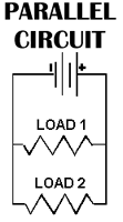
Parallel CircuitsA parallel circuit is one that has two or more paths for the electricity to flow, the loads are parallel to each other. If the loads in this circuit were light bulbs and one blew out, there is still current flowing to the others because they are still in a direct path from the negative to positive terminals of the battery.
|
 |
||||||||
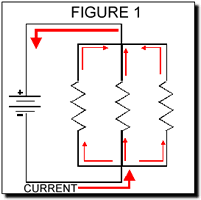
UNDERSTANDING & CALCULATING PARALLEL CIRCUITS - EXPLANATIONA Parallel circuit is one with several different paths for the electricity to travel. It's like a river that has been divided up into smaller streams, however, all the streams come back to the same point to form the river once again. The parallel circuit has very different characteristics than a
series circuit. For one, the total resistance of a Parallel Circuit
is NOT equal to the sum of the resistors (like in a series circuit).
The total resistance in a parallel circuit is always less than any
of the branch resistances. Adding more parallel resistances to the
paths causes the total resistance in the circuit to decrease. As
you add more and more branches to the circuit the total current
will increase because Ohm's Law states that the lower the resistance,
the higher the current. |
 |
||||||||
BASIC RULESA Parallel circuit has certain characteristics and basic rules:
|
|||||||||
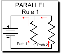
1. "A parallel circuit has two or more paths for current to flow through."Simply remember that PARALLEL means two paths up to thousands of
paths. The flow of electricity is divided between each according
to the resistance along each route. |
 |
||||||||
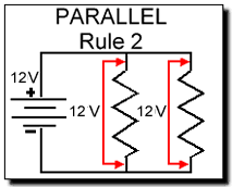
2. "Voltage is the same across each component of the parallel circuit."You may remember from the last section that the voltage drops across a resistor in series. Not so with a parallel circuit. The voltage will be the same anywhere in the circuit. |
 |
||||||||
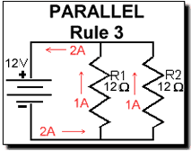
3. "The sum of the currents through each path is equal to the total current that flows from the source."If one path is drawing 1 amp and the other is drawing 1 amp then the total is 2 amps at the source. If there are 4 branches in this same 2 amp circuit, then one path may draw 1/4A (.25A), the next 1/4A (.25), the next 1/2A (.5A) and the last 1A. Don't worry, the next rule will show you how to figure this out.
Simply remember for now that the branch currents must be equal to
the source current. |
 |
||||||||
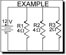
4. "You can find TOTAL RESISTANCE in a Parallel circuit with the following formula: 1/Rt = 1/R1 + 1/R2 + 1/R3 + ... "Before we get into the calculations, remember what we said at the start of this section: "The total resistance of a parallel circuit is NOT equal to the sum of the resistors (like in a series circuit). We will use a parallel circuit with 3 paths as an example (it could be 2, 4 or a 1000 resistors in parallel). The power source is providing 12 volts and the value of the resistors are 5 Ohms, 5 Ohms and 2 Ohms. |
 |
||||||||
Let's summize this EXAMPLE:
Remember that "Rt" means Total resistance of the circuit.
Now we will apply the formula above to this example:
Therefore:
It is easiest to change the fractions into decimal numbers (example 1 divide by 4 equals .25):
Now you have to get rid of the 1 on the left side so...
NOW, Let's try a more complex one:
|
|||||||||
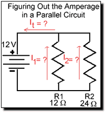
Before we move on to the last rule here's how easy it is to calculate the amperage through each path using OHM'S LAW. In the example we see a 12 and 24 ohm resistor in parallel with a 12 volt source. First we figure out the total resistance of the circuit: 1/Rt = 1/12 + 1/24 |
 |
||||||||
Now that you know this you can figure out the total amperage (It) using Ohm's Law: I total (It) = 12V / 8 Ohms = 1.5 Amps Therefore the total amperage between the two resistive paths must equal 1.5 Amps (Rule 3). Now we can figure out exactly what each path is pulling using Ohm's Law once more. Remember that the voltage is the same everywhere in a parallel circuit. So we know the voltage and the resistance: I1 = 12V / 12 Ohm = 1 A We figured the total amperage (It) previously, so now we can double check if the figures are correct: I1 + I2 = It |
|||||||||
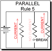
5. "If one of the parallel paths is broken, current will continue to flow in all the other paths."The best way to illustrate this is also with a string of light bulbs in paralallel. If one is burnt out, the others stay lit. |
 |
||||||||